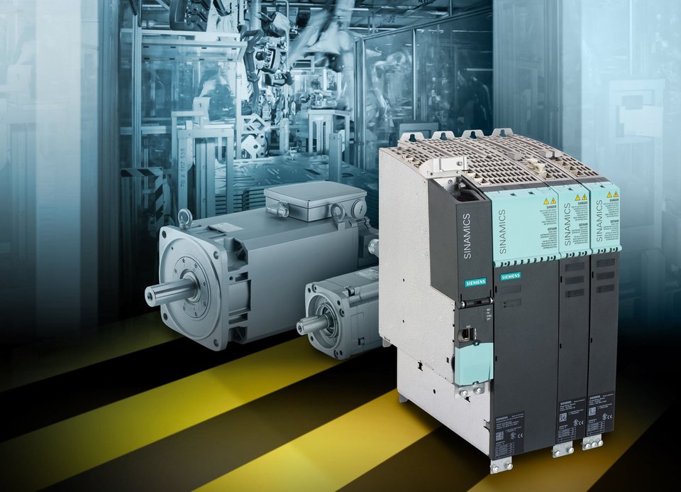
Siemens SINAMICS S120
The flexible, modular drive system for sophisticated applications
SINAMICS S120 modular motion control drives are designed for high-performance drive applications in mechanical and systems engineering. With Siemens' high-performance drive capabilities, you get a range of coordinated components and functions as a complete motion control drive package. Our motion control drives include high-performance single drives and coordinated drives (multiple-axis applications) with vector or servo functionalities that allow implementation of customised high-performance drive solutions. With SINAMICS S120 motion control drives, you get a high-performance drive that is flexible and increases productivity.
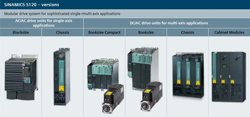
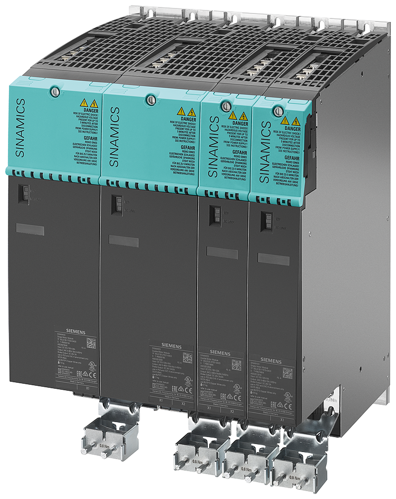
The S120 range is split into single-axis 'AC/AC' and multi-axis 'DC bus' hardware groups. The single-axis products include CU310 and CU310-2 Control Units, and PM340 Power Modules. The multi-axis products include Basic Line Modules, Smart Line Modules, Active Line Modules, CU320 and CU320-2 Control Units, and Single and Double Motor Modules.
Strengths:
- The servo- and vector drive is the perfect basis for modular system and machine concepts.
- Innovative system architecture and digital communication options.
- Broad range of control modes.
- Integrated technology functions.
- Safety functions built into the motion control drives.
- Integrated Know-how protection.
- Efficient engineering and quick commissioning with SIZER drive sizing and STARTER commissioning tools.
- Auto-configuration and auto-tuning of controls.
- Uncomplicated, integrated solutions using Totally Integrated Automation (TIA).
- Integration of SINAMICS through to automation level.
- Integrated SINAMICS S120 web server.
- Extended range of formats from Blocksize through Booksize and Chassis up to the distributed mechanical design of the S120M, which does not have to be accommodated in a control cabinet.
Typical Uses:
Whether it is a continuous goods transport line or synchronized and highly dynamic process, the high performance drive products from Siemens deliver every time and in many industrial applications including:
- packaging machines
- plastic machines
- textile machines
- printing machines
- paper machines
- lifting gear
- handling and assembly systems
- machine tools
- conveyor technology
- rolling mill
- presses,
- ship's drives
- drilling machines.
SINAMICS S120 – now with new Firmware 4.8:
The SINAMICS S120 converter system is provided with a new Firmware 4.8 extending the hardware support by the following devices:
- The Power Modules PM240-2 in frame sizes FSD - FSF
- The SIMOTICS S-1FG1 servo geared motors
- System redundancy with SIMATIC S7-400H
- The SIMOTICS reluctance motor
It provides the following new functionalities:
- Cogging torque compensation allows improved control accuracy
- Active dampening of vibrations with and without load encoder reduces wear on mechanical parts and increases the dynamic response
- Safety Integrated functionalities (brake ramp monitoring with encoder, SIL 3 via Power Modules PM240-2)
| Voltage and power ranges | 0.12 - 5,700 kW 1AC 230 V, 3AC 380 - 480 V and 3 AC 500 - 690 V (50/60 Hz) |
| Control principle: | V/f open-loop control, Vector control with/without Encoder, Servo control with/without encoder |
| Cooling: | air and liquid cooling |
OUR PARTNERS
Authorised Distribution Partner For